Setting up a blitzortung.org lightning detector
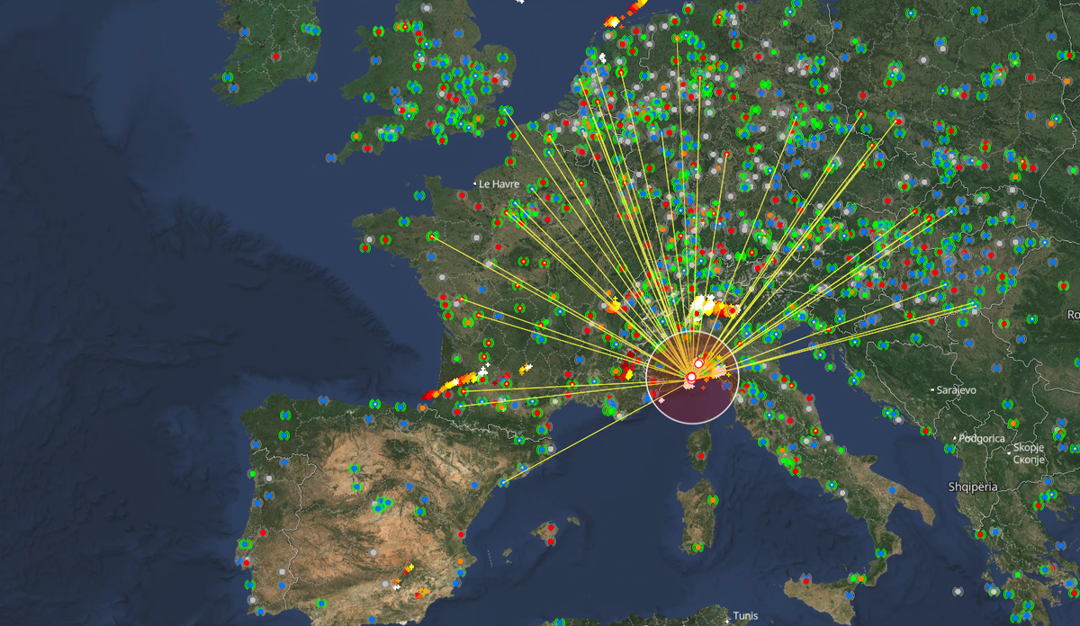
Before getting into the hardware, it is useful to understand how Blitzortung works.
Lightning discharges generate short but very strong electromagnetic pulses that can travel over very long distances, especially in the VLF and LF frequency ranges. A Blitzortung station uses magnetic antennas, such as ferrite rods, to receive these pulses.
A single station cannot accurately determine where a lightning strike occurred. Instead, it records the exact arrival time of each detected pulse using a GNSS/GPS receiver as a precise timing reference. The signal is then sent to the Blitzortung network, where it is compared with measurements from other stations.
If the same lightning pulse is received by several stations at slightly different times, the network can calculate the position of the strike using a Time of Arrival, or TOA, method. In simplified terms:
Lightning strike
      │
      ├──── Station A: 12:00:00.123456
      ├──── Station B: 12:00:00.123812
      └──── Station C: 12:00:00.124105
                         │
                         ▼
               Blitzortung servers
                         │
                         ▼
                Estimated position
This is why the GNSS receiver is an essential part of the station. It is not mainly there to determine the station's geographical position, but to provide a very accurate time reference so that measurements from different stations can be compared.
The Blitzortung network is therefore based on a large number of relatively simple receivers working together rather than on individual stations trying to locate lightning strikes by themselves.
First of all, you need a Blitzortung.org station. These can be purchased directly from Blitzortung by email for around €320. You can find more details on their website and, in particular, in the ordering PDF.
I purchased the latest hardware available at the time: the System Blue Basic, based on the PCB 22.2b controller board.
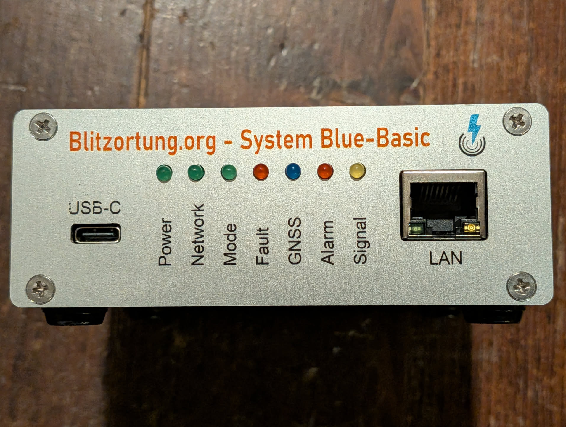
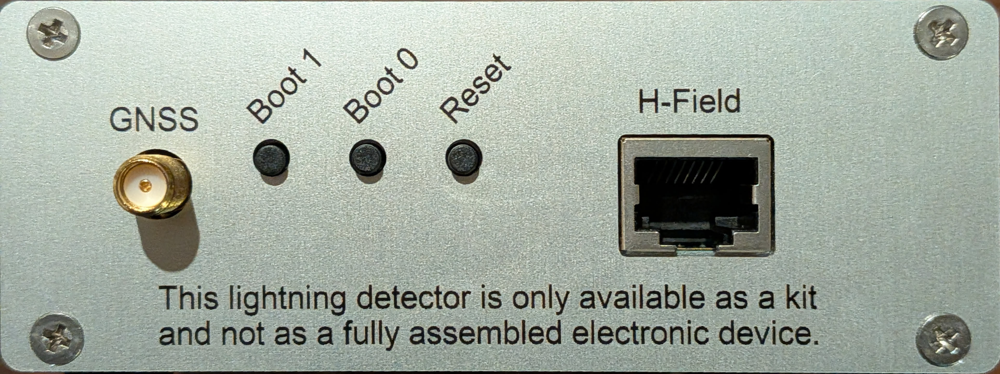
Having the device itself is a good start, but a few additional components are required to get the station up and running. You will need a GNSS/GPS antenna with an SMA male connector, an Ethernet connection to your home network for internet, and another well shielded Ethernet cable (not UTP) to connect the station to the antenna preamplifier.
You will also need two ferrite rod antennas. Following the recommendation included in the ordering documentation, I bought mine from Ferrite Rod Antennas for around €90.
It is probably possible to build the ferrite antennas yourself, but I did not feel knowledgeable enough to do so reliably.
The station comes with a preamplifier to which the two ferrite antennas are connected directly. The preamplifier is then connected to the Blitzortung station using an Ethernet cable. This makes it possible to place the antenna assembly some distance away from the station itself and, more importantly, away from potential sources of electrical interference.
To avoid reception blind spots, the two ferrite rods should be installed horizontally and at a 90° angle to each other, as recommended in the installation guide. They do not need to be aligned with any particular compass direction.
A simple and common way of doing this is to secure both rods to a wooden board using cable ties:
        Ferrite 1
            │
            │
            │
              ───────── Ferrite 2
Another option is to build a 3D-printed enclosure, such as this model on MakerWorld.
This particular enclosure appears to have been designed primarily for vertical mounting, which is not the recommended orientation for the ferrite rods. However, the enclosure itself can simply be installed horizontally, keeping both ferrite rods flat and perpendicular to each other as recommended by Blitzortung.
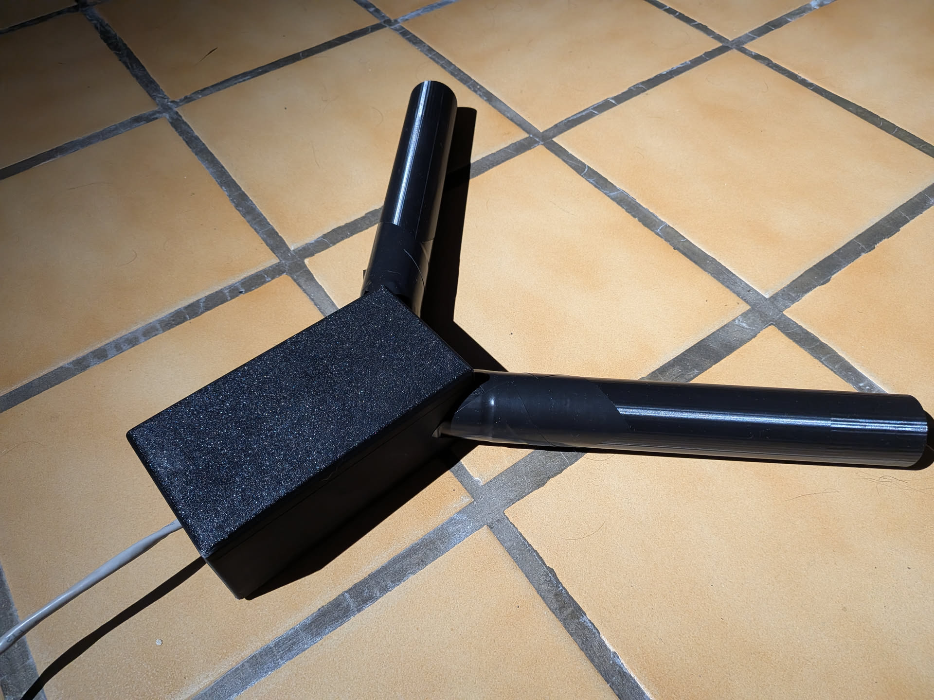
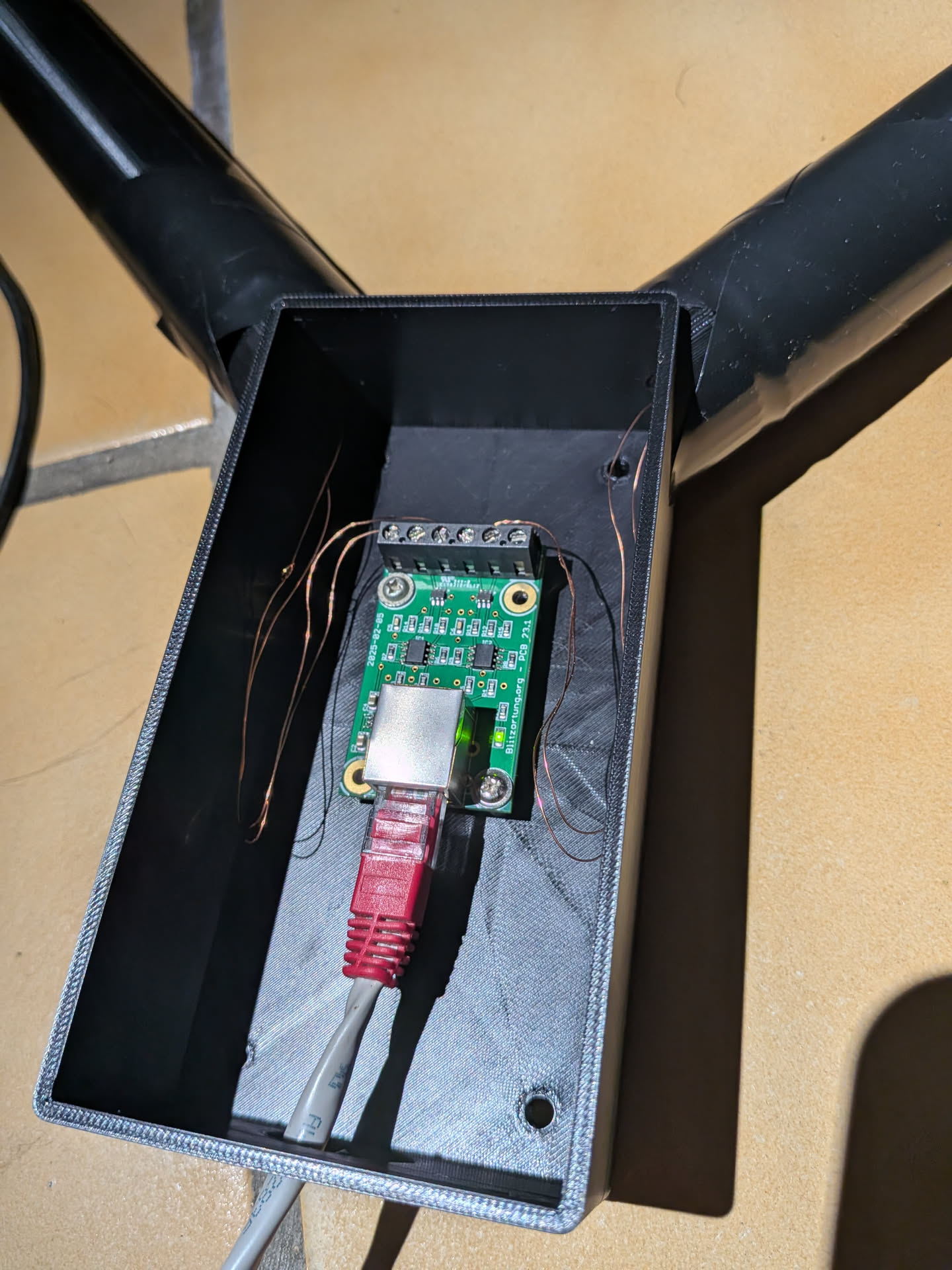
The print of one of the antenna tubes failed near the end due to a mistake on my part, so I used some tape to make sure the ferrite rod could not slide out. Since the whole assembly will be installed in a dry and protected area in my attic, this should not cause any issue.
When connecting the ferrite rods to the preamplifier, make sure to use the four central terminals, which form the two differential antenna inputs. The two outer terminals are ground connections and should not be used for the ferrite windings.
Each ferrite rod simply connects across one pair of antenna inputs:
GND | H1+ | H1- | H2+ | H2- | GND
      └───────┘   └───────┘
      Ferrite 1   Ferrite 2
If your ferrite antennas have one wire marked with a small knot, you can use the same orientation for both antennas for consistency, although the polarity is not critical for normal operation.
Software setup
Once the hardware is assembled, the software setup is fairly straightforward. The Blitzortung controller exposes a web interface directly on the local network, so there is no additional software to install on a computer.
After connecting the station to Ethernet and powering it on, find the IP address assigned to it by your DHCP server and open it in a browser.
The first thing to check is that the controller can communicate with the Blitzortung servers and that your station ID is correctly associated with your account. The status page provides most of the information needed to verify that everything is working correctly.
At this stage, my station was already able to receive and process signals, even before I had installed the GNSS antenna. However, those signals cannot be used for lightning localization without an accurate GNSS time reference.
GNSS configuration
The GNSS receiver is a critical part of the system. Its main purpose is not simply to determine the geographical position of the station, but to provide a highly accurate 1PPS timing signal.
Blitzortung compares the arrival time of the same lightning pulse at multiple stations. Without accurate timing, the server cannot use the received signal to calculate the position of the lightning discharge.
Once the GNSS antenna is connected, the status page should eventually report a valid position and a valid 1PPS signal. The antenna should ideally have a reasonably clear view of the sky. Depending on the construction of the roof, installing it inside an attic may still work perfectly well.
Configuring the H-field channels
The two ferrite rods appear as two H-field channels in the web interface.
For my installation, due to poor performances in full automatic, I switched the station to manual mode while keeping Noise Adaption enabled. This allows the controller to automatically reduce the effective sensitivity when the local noise level increases.
My current amplifier configuration is:
Channel A
Gain: 8 × 2 × 40 = 640
Noise: approximately 19 mVpp

Channel B
Gain: 8 × 2 × 40 = 640
Noise: approximately 20 mVpp
The two channels having similar noise levels is a good sign, as both antennas are installed in the same environment and use identical ferrite rods.
Blitzortung recommends adjusting the gain so that the observed noise level is roughly in the 20 to 25 mV range. In my attic, a total gain of 640 puts both channels very close to this target.
The trigger threshold is currently around:
-78 mV / +78 mV
With this configuration, the station only sees a few triggers per second under normal conditions, while still keeping enough sensitivity to detect distant lightning signals.
Noise and interference
The web interface also provides useful tools to diagnose electromagnetic interference.
One of the most useful views is the frequency spectrum. This makes it possible to detect continuous signals generated by switching power supplies, LED drivers, computers, solar equipment or other electronic devices.
In my case, there is a particularly strong signal around 20 kHz:
                 █
                 █
                 █
─────────────████████─────────────
              ~20 kHz
A narrow and stable signal like this is not necessarily generated by equipment inside the house. The VLF spectrum contains several powerful transmitters that can be received over very long distances.
Because of this, it is better to investigate the source before trying to filter it. A simple test is to temporarily power the Blitzortung station from a battery and switch off the electrical circuits in the house. If the signal remains, it is probably coming from an external transmitter rather than from local equipment.
The station also includes automatic interference detection. Under normal conditions, my interference filter remains in the Idle state, which indicates that the local electromagnetic environment is reasonably clean.
Filters
I currently use:
Noise Adaption      Enabled
Interference Filter Enabled
DSP Filter          Enabled
The DSP view is particularly useful during the initial installation because it provides frequency-domain information that can help identify interference.
There is also a Peak Band Filter, but it is intended for specific repetitive interference patterns rather than normal broadband noise. Unless you have a particular interference problem that requires it, it is generally better to leave it disabled.
Once the installation has been running reliably for a while, the DSP processing can also be disabled if the spectrum monitoring is no longer required.
What to monitor
The main status page provides a few useful values to keep an eye on:
Signals Received
Good
Sent

Noise level
Trigger rate
Amplifier gain

Interference status

GNSS availability
1PPS accuracy

CPU load
Input voltage
Network status
A healthy installation should normally show similar noise levels on both H-field channels, a relatively low trigger rate when there is no thunderstorm activity, and no permanent interference condition.
Once GNSS synchronization is available, the most interesting metric becomes the number of signals actually sent and used by the Blitzortung network.
At that point, the best way to evaluate the installation is simply to let it run. After a few thunderstorms, it becomes much easier to determine whether the gain is appropriate, whether there are local sources of interference, and how well the station performs compared with nearby Blitzortung stations.
Securing the interface
The Blitzortung web interface is intended primarily for local administration. If the controller is only accessible from a trusted LAN, this is usually sufficient, but it is still a good idea to enable authentication if the firmware provides the option.
The controller should not be exposed directly to the Internet.
Once the GNSS receiver is synchronized, the two H-field channels are properly adjusted, and communication with the Blitzortung servers is established, there is very little maintenance required. The station can simply remain powered on and continuously contribute measurements to the network.
Do you want to discuss about it? Feel free to join my discord server